|
|
||||||||||||||||||||||
Sigma Projection |
||||||||||||||||||||||
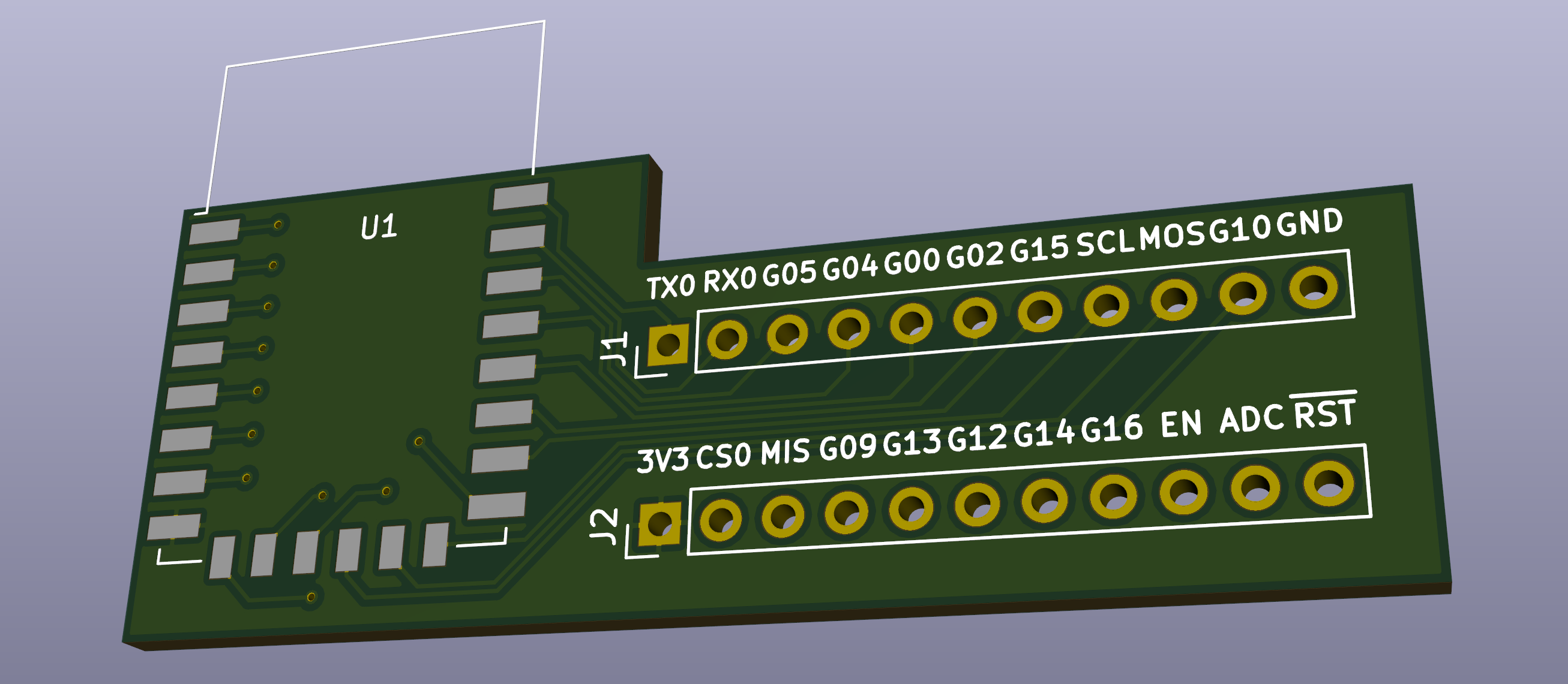
ESP-12E \ ESP-12F Adapter PCB for BreadboardThis page contains set of ESP-12E \ ESP-12F adapter PCB design files. Presented PCB allows to plug ESP-12E(F) module into breadboard, making your design tests more convenient. Solution is created under KiCad 5.0.2 environment. Source KiCad project and Gerber files are available on GitHub: [ ESP-12-E(F) Breadboard Adapter PCB ]
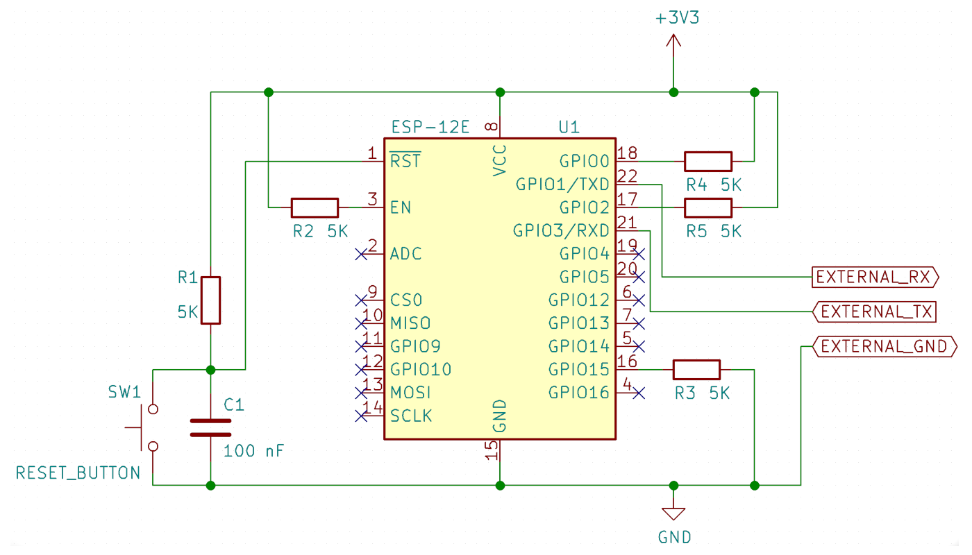
Gerber files can be downloaded from this site as well: [ ESP-12E(F) Adapter PCB: Gerbers ] ESP-12E connectivity schemaESP module needs to be powered up by 3.3V rail. Also there is a need to make sure 3.3V rail can provide sufficient amount of current (otherwise ESP module will be constantly rebooting). In order to use this module the following connection schema can be assembled:
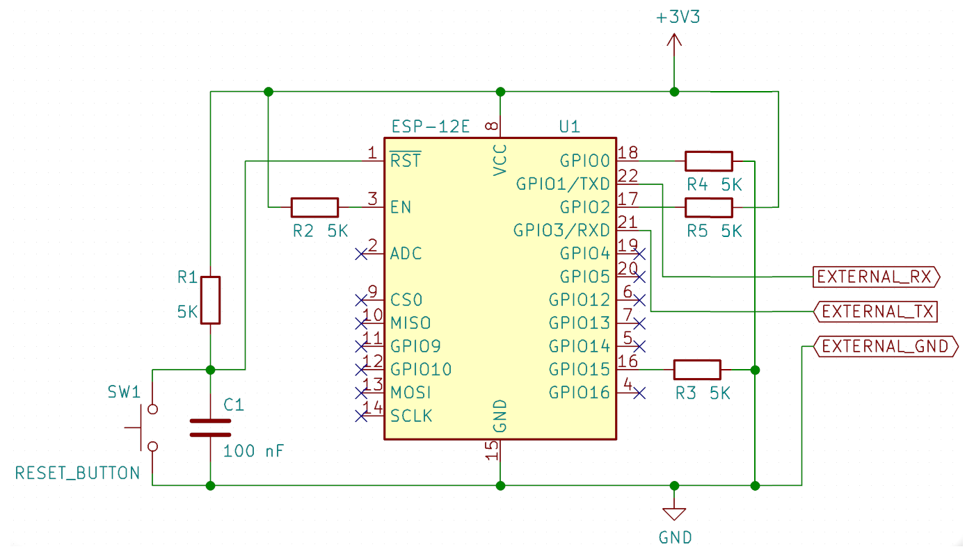
Schema above represents the way how ESP module should be connected in order to execute application. In case of application needs to be flashed into ESP chip - the corresponding GPIO 0 pin needs to be pulled down to ground:
C1 100nF capacitor is responsible to keep RST line stable. In case of SW1 button click - C1 will be discharged and RST line will be pulled to ground, which will cause ESP chip to reboot. Set of 5K resistors is presented here to create corresponding
ESP GPIOs pull-up\pull-down configuration. All necessary details about different pins configuration modes you can find on ESP-12E\F module documentation: ESP-12E application building, flashing and executing. Workflow details with ESP manual reset option.Presented PCB design does not offers auto-reset ESP feature. Hence, before each flash\run application step, chip reset needs to be performed manually. Flashing shell scripts below allow to make manual reset step between build cycles. The first shell script sample will erase ESP memory. Memory clean-up is an optional step - it can be triggered before actual application flashing into ESP chip:
# Please update parameters below in accordance with your TTY\Pip\Python\EspSDK configuration
PORT=/dev/serial/esp8266
PYTHON=/usr/bin/python2.7
ESP_TOOL=~/.local/bin/esptool.py
FW_BIN_DIR=~/esp8266-dev-kits/esp-native-sdk/bin

if [ ! -c $PORT ]; then
  echo "ERROR: No USB tty device found"
  exit 1
else
  echo "INFO: Using USB tty device: $PORT"
fi

echo
echo "INFO: Erasing Flash Memory... "

$PYTHON $ESP_TOOL --chip esp8266 --port $PORT --baud 115200 --before no_reset --after no_reset erase_flash

if [ $? -eq "0" ]; then
  echo "INFO: Done Erasing. Please reset your ESP module before the next step."
else
  echo "ERROR: Unable to complete \"Erase Flash Memory\" step"
  exit 1
fi
And the following shell script will flash actual application (please note to update parameters PORT, PYTHON, ESP_TOOL, FW_BIN_DIR based on your specific SDK configuration - as described at ESP introduction page here):
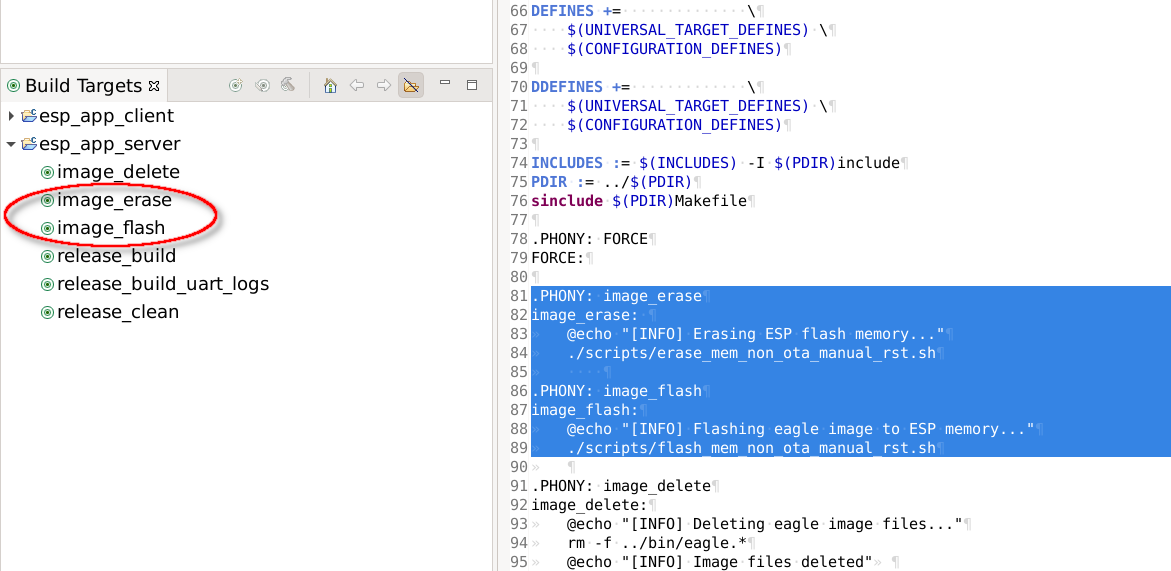
# Please update parameters below in accordance with your TTY\Pip\Python\EspSDK configuration
PORT=/dev/serial/esp8266
PYTHON=/usr/bin/python2.7
ESP_TOOL=~/.local/bin/esptool.py
FW_BIN_DIR=~/esp8266-dev-kits/esp-native-sdk/bin

if [ ! -c $PORT ]; then
  echo "ERROR: No USB tty device found"
  exit 1
else
  echo "INFO: Using USB tty device: $PORT"
fi

echo
echo -n "INFO: Flashing Firware... "

$PYTHON $ESP_TOOL --chip esp8266 --port $PORT --baud 115200 --before no_reset --after no_reset write_flash --flash_freq 20m --flash_mode dio --flash_size detect --verify 0x000000 "$FW_BIN_DIR/eagle.flash.bin" 0x010000 "$FW_BIN_DIR/eagle.irom0text.bin" 0x3FB000 "$FW_BIN_DIR/blank.bin" 0x3FC000 "$FW_BIN_DIR/esp_init_data_default_v08.bin" 0x3FE000 "$FW_BIN_DIR/blank.bin"

if [ $? -eq "0" ]; then
  echo "INFO: Done Flashing. Please pull-up GPIO0 pin and reset your ESP module to run the application."
else
  echo "ERROR: Unable to complete \"Flash Memory\" step"
  exit 1
fi
All of these steps can be configured as corresponding Eclipse build targets:
Below is the full build\flash sequence presented. It can be used for ESP12-E(F) modules with manual reset option:
|